
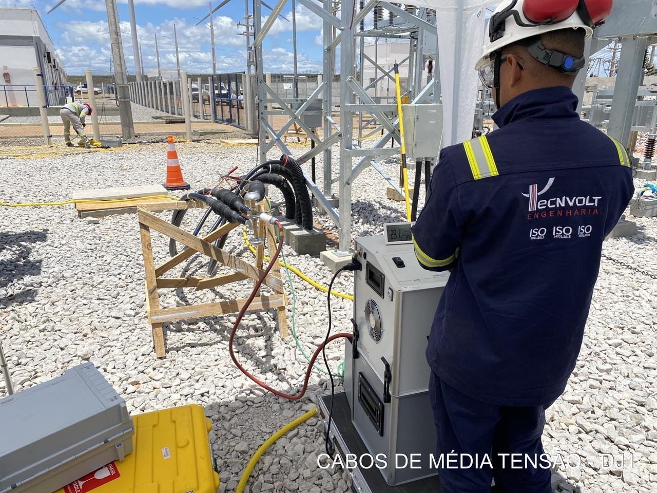
VLF cable testing (Very Low Frequency withstand testing) is the industry-standard method for proving the dielectric integrity of medium voltage underground cables after installation, repair or as part of a condition-based maintenance program. Performed in accordance with IEEE 400.2-2024 and referenced by ANSI/NETA ATS and MTS, a VLF withstand test applies an AC voltage at 0.1 Hz to stress the cable insulation system – conductor, insulation, joints and terminations – and confirm it can withstand service conditions without breakdown.
Why VLF testing instead of DC hipot
For decades, DC hipot testing was the default field test for cable insulation. Research consolidated in IEEE 400 demonstrated that DC testing is ineffective on extruded (XLPE and EPR) cables and can even be harmful: DC stress leaves trapped space charges in the insulation that accelerate water tree growth and can trigger failures after the cable is returned to service. VLF testing solved this problem. By applying a true AC waveform at very low frequency, the required test power drops by a factor of roughly 500 to 1000 compared to power frequency, allowing long cable runs to be tested with compact, portable equipment – without the damaging effects of DC on aged extruded insulation.
What a VLF withstand test verifies
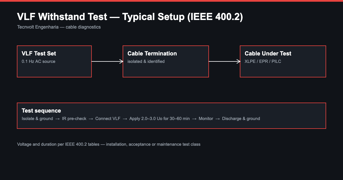
The VLF withstand test is a pass/fail proof test. The cable system is energized at an elevated AC voltage – typically 2.0 to 3.0 times rated phase-to-ground voltage depending on cable class and test type (installation, acceptance or maintenance) – for a defined duration, normally 30 to 60 minutes per IEEE 400.2 tables. If the insulation contains a critical defect such as a severe water tree, a poor joint or damaged insulation, the defect is driven to controlled breakdown during the test, when repair is cheap and planned – instead of failing in service, when an outage is expensive and unplanned.
Test procedure
A professional VLF test campaign follows a disciplined sequence: isolation and grounding of the cable under test; verification of phase identification; insulation resistance measurement as a pre-check; connection of the VLF test set to the cable termination; voltage application with programmed ramp and hold per IEEE 400.2; continuous monitoring of leakage current and waveform; and controlled discharge and grounding at the end of the test. Results are documented per phase, with test voltage, frequency, duration and outcome recorded for the asset history.
Combining VLF with diagnostics
A withstand test alone answers one question: did the cable survive? Combining VLF with Tan Delta (dissipation factor) measurement and partial discharge testing during the same mobilization transforms a pass/fail test into a full condition assessment. Tan Delta quantifies global insulation aging (water treeing), while PD locates discrete defects in joints and terminations. This is the Monitored Withstand Test (MWT) approach recommended by IEEE 400.2 – and it is the core of the Tecnvolt cable diagnostics methodology.
Standards we follow
Our VLF testing is performed per IEEE 400.2-2024 (Field Testing of Shielded Power Cable Systems Using Very Low Frequency), with acceptance criteria and test voltages aligned to ANSI/NETA ATS (acceptance) and ANSI/NETA MTS (maintenance). Equipment: BAUR VLF generators with integrated Tan Delta measurement, calibrated and traceable.
What you receive
Every VLF campaign is delivered with a complete technical report: cable identification and route data, test parameters per phase, measured values, pass/fail assessment against the applicable standard, and clear recommendations – repair, retest interval or replacement planning. Reports are engineering-grade documents suitable for asset management systems, insurance and regulatory files.
When to specify VLF testing
Typical applications include: commissioning of new MV cable installations before energization; acceptance testing after cable repair or joint replacement; maintenance testing of aged circuits in industrial plants, data centers, ports and utility networks; and due diligence assessment of critical feeders before load increases. For circuits where an outage is costly, the combination of VLF withstand with diagnostics provides maximum information per outage window.
Why Tecnvolt
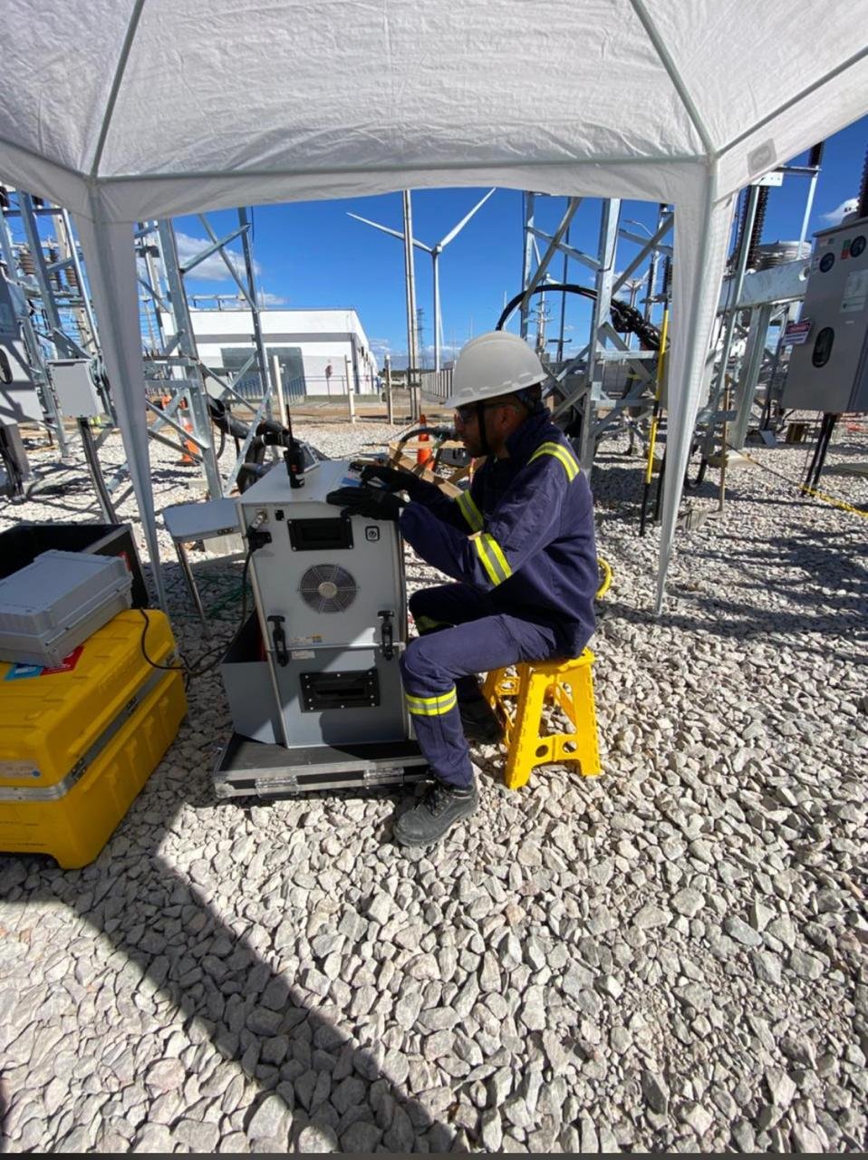
Tecnvolt Engenharia has performed cable testing and diagnostics since 2012 under the same standards (IEEE 400.2, ANSI/NETA) and the same equipment platforms (BAUR) used across the U.S. market, serving oil and gas, heavy industry, ports and utilities from low voltage to 500 kV substation environments. The company is certified to ISO 9001, ISO 14001 and ISO 45001.
Frequently asked questions
How long does a VLF test take? Typically 30 to 60 minutes of voltage application per phase, per IEEE 400.2, plus setup. A three-phase feeder is normally completed within a single shift.
Can VLF testing damage a good cable? No. A cable in sound condition is not degraded by a correctly applied VLF test. Only insulation already containing critical defects will break down – which is precisely the purpose of the test.
What cable types can be tested? Extruded XLPE and EPR cables, paper-insulated (PILC) circuits and mixed circuits, at MV and HV classes, subject to test set capacity and IEEE 400.2 guidance.
About our U.S. transition
Tecnvolt Engenharia is a Brazilian company founded in 2012, currently in the process of establishing a U.S. company in Houston, Texas. During this transition we are receiving inquiries and scheduling future work. Request a quote / register interest